

Impedance Matching | ThinkRobotics.in
Impedance matching is the process of simply making one impedance look like another. In high-frequency PCB design, Impedance matching means that when energy is transmitted, the load impedance must be equal to the transmission line's Characteristic impedance.
Normally, it becomes necessary to match a load impedance to a driving source's source or internal impedance.

That's where Impedance matching is playing its role. That message was displayed mostly because your laptop or smartphone's input impedance did not match the device you were trying to connect, like a floppy disc or a pen drive.
The process for impedance matching in high-speed PCB designs depends on the signalling standard, supply voltage levels, and signal levels.
Principle:
According to the maximum power transfer theorem, when the load resistance is equal to the source resistance and load reactance is equal to the source reactance's negative, the maximum power is transferred from source and load. It means that the maximum power can be transferred if the load impedance is equal to the source impedance is complex conjugate.
In the case of the DC circuit, the frequency is not considered. Hence, the condition is satisfied if the load resistance equals the source resistance.

Thus, matching the impedance leads to maximum power transfer to the load circuit and minimizes the negative effects of the reflection on the signal.
These reflected waves matched with the transmitted signals, causing delays in data, phase distortion, and reducing the ratio of signal to noise.
Characteristic Impedance:
Characteristic Impedance (Z0) is the resistance in parallel circuits and power planes to current (AC) flow. The Characteristic impedance of a uniform transmission line is the ratio of the amplitudes of voltage and current of a single wave along the line. It is determined by the geometry and materials of the transmission line. The unit of Characteristic impedance is the ohm.
The various factors that determine the Characteristic Impedance of the trace/Transmission line on a PCB are-
The width of circuit trace, the thickness of circuit trace, dielectric thickness-thickness of the core, prepreg or solder mask around the circuit trace, the dielectric constant of the material, solder mask thickness, and its Dk value. Also, model reliability, measurement integrity, process control and capability, defined work instructions, lab analysis, etc.
Resistance, capacitance, inductance, and conductance are the parameters that determine the Characteristic impedance of a transmission line or even a trace. The parameters are connected in the manner, as shown in Fig 3, and the magnitude of the Characteristic Impedance they possess on the circuit.
At high frequencies, resistance and conductance have negligible effects. The Characteristics Impedance for a lossless line is given as,
ZO = √(L/C)
Above about 50 MHz, the Characteristic impedance of a transmission line is constant with frequency. This is the “high-frequency” Characteristic impedance and is the value typically used for all evaluation of high-speed signals' behavior.

Impedance Discontinuity:
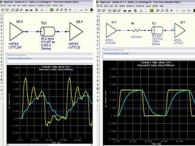
A transmission line or even a small PCB trace should have a Characteristic uniform impedance. Any variation or discontinuities to the impedance causes the signal reflection, ringing, and distortion. Consequently, at high switching frequencies, the distortion caused to digital signals by impedance discontinuities can be so severe that signal sampling errors may occur.
Common causes of Impedance Discontinuity:
- Any disruption in the return line or ground plane of signal in the PCB that forces the return signal to deviate from its route will cause an Impedance discontinuity.
- In PCB, one signal is passed to more than one destination. This, even if necessary, undeniably splits the signal path, causing splitting of the impedance, giving rise to discontinuity.
- Any change in the line's impedance, due to whatsoever reason, directly or indirectly changes the capacitance and inductance of the line, resulting in Impedance discontinuity.
- The Use of Vias is necessary for PCBs; it changes the capacitances and inductances of the lines/traces, causing discontinuities.

The only way to overcome this is to ensure that the Characteristic impedance is the same at all points on the signal path.
- The return paths and ground planes for returning the signal must be secured.
- Avoid branches as much as possible. This will reduce the splitting of the Characteristic Impedance.
- Impedances of all three -source, line/trace, and load are equal.
- The Use of the Micro vias instead of the traditional ones will help.
- Ensure changes in the PCB are so made that they have a minimum effect on the impedance and capacitance value-line/trace.
The Use of a standardized impedance such as 50 Ω and 75 Ω makes high-frequency PCB designs such as Radio-frequency design very much practical and efficient. Most RF systems are built around 50 Ω impedance and sometimes on75 Ω, used for more accurate high-speed digital signals.

Voltage Matching & Bridging Inputs:
In the telecommunication industry, the realization of impedance Matching almost a century ago proved very efficient. Thus, the broadcasting industry, and later the recording industry, grew up directly from the telecoms industry's technology – based on the necessity of matching the impedances.
As a result, the early broadcast and recording studios also used the 600Ω matched-impedance principle, which was then the standard in the telecommunication industry for almost all — tape machine outputs, console inputs, etc. Yet, the idea of matching impedances is not exactly good or practical in a recording studio because
- In a recording studio, we are more interested in the information carried by the signal and, more precisely, the number of voltage fluctuations in the signal.
- Besides, unlike in the telecommunication industry, where the distance between the source and the load is merely a few meters.
Thus, the use of impedance matching was futile.
This gave rise to another technology called Voltage Matching. It involves the equipment to have the lowest possible output impedance and relatively high input impedance; the difference between them must be at least a factor of 10 and is often much more practical.
Say the output impedance is chosen to be 150 Ω then the input impedance close to 1.5 kΩ to 3 kΩ.
Relatively high-impedance inputs such as these are called bridging inputs. They have the pros of the ability to connect several devices in parallel without decreasing the impedance to any significant value. The voltage developed across each input remains high, and the source does not need to supply the high current. Low impedance is called loading the output or circuit.
Now let us see how the impedance is managed in various recording devices.
Microphones & Preamplifiers:
The early ribbon microphones used the impedance matching technology, operating at the then standard values of impedances. Later on, with the discovery of capacitor microphones and their internal impedance converting head amplifiers, the inkling of voltage matching was adopted and is retained to date irrespective of the microphone type.

Thus, most microphones have an output impedance of 150-200Ω. Most preamplifier inputs offer an input impedance of between 1.5kΩ and 3kΩ.also; it is recommended not to keep the input impedance of the mic very high, as the higher the resistance, the greater is the noise.
Electric Guitars:
and electric guitar‘s circuit employs the voltage impedance circuitry. The pickups in guitars and basses are primarily inductive rather than capacitive and are also highly resistive (typically up to 10kΩ) merely because of a lot of wire involved. Since the pickup possesses a relatively high output impedance, the use of preamp and DI inputs with a hugely high input impedance comes along.

A minimum value of the input impedance could be 470kΩ, but many are over 1MΩ and a few, pickups in some acoustic guitars, possess even higher value.
Loudspeaker Loudspeakers are very complicated things, and those with passive crossovers are often challenging for the amplifier(s) to drive. Often, the loudspeaker manufacturers plot the curve of impedance VS frequency plots of their products for the user's convenience.
The impedance of the connecting cables can affect sound quality. Using good-quality, thick, heavy-duty two-core mains cables that are terminated properly, the cable resistance will be sufficiently low.
Headphones:
The design of its voice coils determines the impedance of a headphone: the length and size of wire used, the number of turns around the former, the magnet's strength, and so on. Thus, the headphone's impedance and design, along with the amplifier used, will affect the volume produced.
The headphone's sensitivity in terms of decibels per milliwatt (dB/mW) gives us the exact required info about the quality of the volume produced.
Mainly, headphones can be categorized into three groups based on their impedance:
- Broadcast- 1.5kΩ and 2kΩ.
- Professional –150Ω to 600Ω.
- Portable- 8Ω to 32Ω
Audio Metering, Video & Digital Audio:
In general, outboard meters, be it a proper test and measurement devices, or just external meters of some kind, are designed with high input impedances. This is to be connected across an audio circuit without loading it and affecting its level. Because you do not wish to change the signal you are planning to measure!
With the everyday voltage-matched interface arrangements, there is nothing to worry about. One can simply plug the meter across an audio circuit and done. However, when impedance matched interface is used, faulty results are produced if the test and measurement meters are often not furnished with a switchable 600Ω termination facility.
The practice of using 600 Ω is rare these days. Instead, you will indeed find Video interfaces operating with 75Ω matched-impedance connections.

At times we need to connect multiple devices to a single output, which is not strictly allowed in a matched-impedance system. One of the solutions to this issue is to connect the inputs of the destination equipment in parallel, with only the last providing the necessary 75Ω termination, and the others all present a very high input impedance. Since we know that the parallel connection of several impedances results in the least value impedance as the equivalent impedance of the whole connection, this tricks the source into considering the connection of only 75 Ω, Thus, not disrupting the rule of matched impedances.
Sources:
- allpcb.com/Characteristic_impedance.html
- protoexpress.com/blog/impedance-discontinuity-signal-reflection-pcb-transmission-lines/
- nwengineeringllc.com/article/impedance-matching-for-high-speed-signals-in-pcb-design.php
- medium.com/@PCBWay/impedance-matching-in-high-speed-pcb-design-9f070db8b8f4
- informit.com/articles/article.aspx?p=2916283&seqNum=19
- images.app.goo.gl/gwNzt8xpNZnsu8cT7
- images.app.goo.gl/fVtFWo1UmkvV8Xzz8
- images.app.goo.gl/xiymexd8AZuzS6qi8
- mgc-images.imgix.net/pcb/tlines.jpg-11f62c5e-5a9d-4dd2-92a7-8c22a7499616.jpg?q=60&fit=max&w=600
- images.app.goo.gl/rQS4TQdhf1Qa4WBW9
- images.app.goo.gl/wn8qKEdtLVtrswJj8
- images.app.goo.gl/REECUYABcWWA1bR58
- images.app.goo.gl/zfbZU4EfXdYi9wQE9
